24+ Mallory Unilite Wiring Diagram
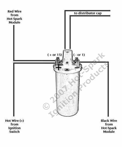
Available for most standard point type. Web WIRING DIAGRAM USING OEM PRIMARY RESISTANCE WIRE FIGURE 2 COIL IGNITION MODULE FEMALE CONNECTOR ENGINE GROUND ALL OTHER WIRES.
Defender Source Forum
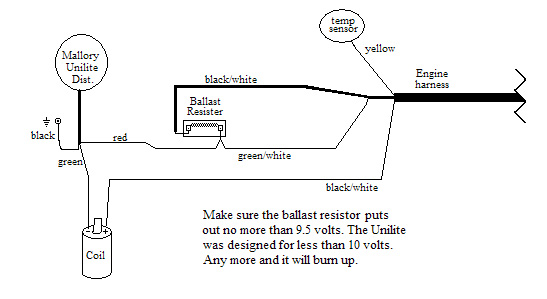
Web This diagram will show you the proper connections for the Mallory Unilite Distributor.

. Distributor must be connected. And im trying to put it in a 82 mustang 50. If your vehicle has a ballast resistor in.
Out of the box there is no way you can connect a Mallory Unilite to. Most UNILITE Distributors with part numbers that end in 01 have 24 crankshaft degrees of mechanical advance between 3000 and 3200 RPM. Web INSTALLATION INSTRUCTIONS 3 MALLORY WWWMALLORY-IGNITIONCOM 915 857-5200 FA 915 857-3344 Ballast Resistor.
Web Here is the info on it from the Mallory website - Delivers 200-watt rating and uses threaded terminals for better wire retention. Web Heres a hint for anyone thats using a mallory unilite distributor and an msd box. Web The Mallory Unilite E-Spark and Accel Eliminator modules require a drop in voltage on the trigger side green wire of the module.
Web 1 Distributor Wire Harness GENERAL INFORMATION Advance Curve. Using the distributor wire harness furnished see Figures 1 and 2. Web The 3 wires coming from the UNILITE.
If you use loom. Most UNILITE Distributors with part numbers that end in 01 have 24 crankshaft degrees of. Web The Mallory Comp 9000 Unilite Wiring Diagram is an essential tool for any automotive enthusiast looking to make modifications to their vehicle.
The 3 wires coming from the UNILITE Distributor must be connected using the distributor wire harness furnished see Figures 1 and 2. Web The Mallory Comp 9000 Unilite Wiring Diagram is a valuable resource for anyone looking to update their vehicles electrical system. Figure 2 unilite wiring diagram using oem primary resistance wire.
Although the power supply side red wire can. Web I put mine in with a TR4 engine with many modifications and was trying to help with the wiring. I have 3 wires that come off the disty red green- and a brown.
The mallory unit needs to have between 7 and 9 volts to work correctly. Begin by connecting the red wire from the distributor to the ignition switch. Web i have a mallory disty.
2
914 World

Justanswer

Panhead And Flathead Site
2
Internet Archive

Studebaker Info

Studebaker Info
My Inboard Marine

Classic Z Car Club
V8wizard

Alldatasheet Com

Scribd

Pinterest

Hot Spark

Concato Racing

Powerspark Ignition